The post How SyBridge Expertise Optimizes Your Process and Lowers Costs appeared first on SyBridge Technologies.
]]>
How SyBridge Expertise Optimizes Your Process and Lowers Costs
In the fast-paced world of manufacturing, efficiency is paramount. Every second shaved off a cycle time translates directly to higher profits and a competitive edge. And when it comes to injection molding, tooling design is often the foundation upon which everything rests. At SyBridge, we understand this, and it’s why we’ve become the industry leader in design, engineering, and manufacturing of injection mold tooling.
Our expertise goes beyond simply creating high-quality tools. We are experts in optimization, and our dedication to understanding your specific needs allows us to craft solutions that streamline your entire injection molding process.
A Real-World Example
Supercharging Production
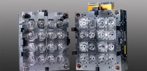
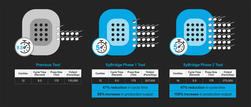
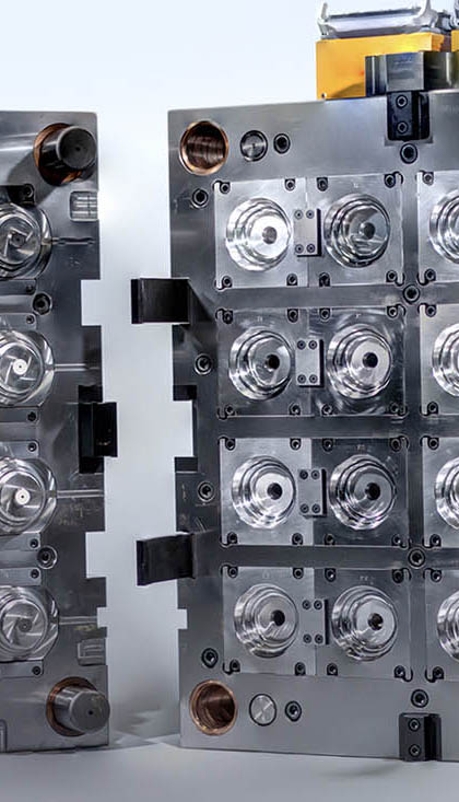
One client, a manufacturer of plastic dosing scoops, faced a common challenge: production couldn’t keep up with demand. They were running four 175-ton injection molding machines 24/7. Each existing 12-cavity tool had a 9.5-second cycle time and produced 110,000 parts per day, but it simply wasn’t enough.
Phase 1
SyBridge engineers evaluated the customer’s existing equipment, systems, and output needs, then designed a new 12-cavity tool using innovative solutions for filling and cooling the component. Upon installation, they realized a remarkable 5.0-second cycle time, a 47% reduction from their previous 9.5-second cycle time. This translated into an 88% increase in daily production with the same machine, producing an impressive 207,000 parts per day.
Phase 2
But SyBridge didn’t stop there. Building on this success, we engineered another tool, this time with 16 cavities; as before, the cycle time was at 5-seconds, and the higher-cavitation tool was still able to run in the same 175-ton presses. This powerhouse pushed daily production even further, reaching 275,000 parts – a 150% increase from the original tool.
The Proof is in the ROI
The impact was undeniable. The manufacturer not only met demand but was also able to get ahead of it, opening up opportunities for new sales growth. SyBridge tooling solutions delivered such significant production gains that the customer was able to recoup their tooling investment in less than 6 months, a testament to the immediate value delivered by SyBridge expertise. But even beyond the initial investment payback, with the increased output, the customer was able to better schedule planned maintenance, extending the life of the tools and leading to additional long-term financial benefits. This is just one example of how SyBridge empowers our partners to achieve remarkable results. Our commitment to precision engineering, coupled with our in-depth understanding of the injection molding process, allows us to:
- Reduce cycle times through innovative tool design, leading to greater output and increased production efficiency.
- Lower your Total Cost of Ownership (TCO) through more efficient tooling that drives lower direct and indirect material costs for molded products.
Ready to unlock the full potential of your injection molding process?
At SyBridge, we are more than just toolmakers; we are your optimization partners. We understand the unique challenges you face and are committed to developing solutions that not only meet your needs but exceed your expectations.
Contact us today to discuss your specific needs and discover how our expertise can help you achieve breakthrough results:
- Faster cycle times
- Increased production output
- Reduced total cost of ownership
- A competitive edge in the marketplace
The post How SyBridge Expertise Optimizes Your Process and Lowers Costs appeared first on SyBridge Technologies.
]]>The post 2024 Trends in Cosmetic Packaging appeared first on SyBridge Technologies.
]]>In this fast-paced market, where consumers crave both luxury and sustainability, staying ahead of the curve is crucial. This article delves into the key trends transforming the industry, from captivating design elements to eco-conscious solutions, empowering you to create packaging that not only looks good but resonates with today’s savvy consumers.
Product differentiation drives sales
In an increasingly crowded marketplace, creating a unique style for cosmetic packaging is key to catching the eye of consumers and building brand loyalty. Consumers look for details in the design, such as embossed logos on caps, custom colors, unique materials like copper and aluminum, and exclusive shapes (Figure 1).
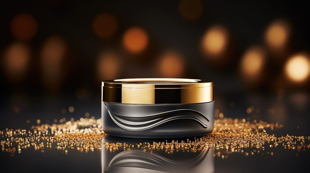
Figure 1. Distinctive shapes and mixed materials help products stand out in the beauty market.
Consumers also expect a luxe feel when purchasing a beauty product with a high price point. Using substantial materials in packaging gives even miniature products a high-end feel.
Additive manufacturing supports new product development
Developing products with novel designs requires expertise and options for scaling if products become popular. Since the cosmetics industry moves quickly, bringing a new product from conception to design to reveal is essential for its relevance. And because customer preferences can pivot rapidly, manufacturing a limited number of new products using cost-effective techniques to test the market is also important.
Additive manufacturing processes like 3D printing meet both requirements—they can produce parts quickly and don’t require huge upfront costs (Figure 2).
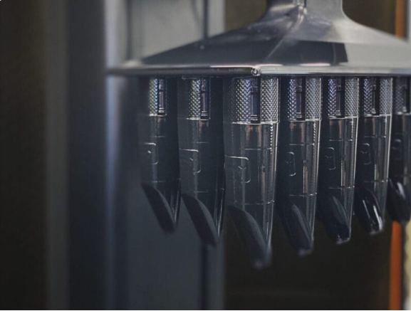
Figure 2. Carbon® Digital Light Synthesis™ is one of SyBridge’s many 3D printing techniques
“SyBridge is unique because we can jump right into product design, support and validation through our 3D printing and additive manufacturing capabilities. Not all companies that provide manufacturing support also provide design services. Having this range of capabilities puts us in the position of helping companies in both the conception and production stages of manufacturing.” – Ramsey Haylett, Life Sciences and Consumer Business Development Manager, SyBridge Technologies
Companies can scale production with high cavitation injection molds or other production techniques if the product is commercially viable. Although specialty tooling capabilities may have a higher upfront cost, their ability to support higher production runs and longer lifetime cycles ensures they remain cost-effective. The ability to start small and scale ultimately results in the lowest overall cost of ownership for brand owners.
Using sustainable materials and designs to appeal to consumers
Sustainability continues to be a trend for consumer products in 2024, including cosmetic packaging. However, most consumers are unwilling to compromise on increased prices for more sustainable products. Manufacturers must find a way to produce sustainable packaging that is also cost-effective.
Toward more sustainable cosmetic packaging
Refillable and reusable packaging is emerging as a more environmentally friendly alternative to single-use packaging. Other sustainability trends include using either post-consumer recycled (PCR) plastic or aluminum for manufacturing or creating products made of single, recyclable plastics (mono-material) instead of a mixture of plastic and metal (Figure 3).

Figure 3. Material selection simplifies sustainability for consumers
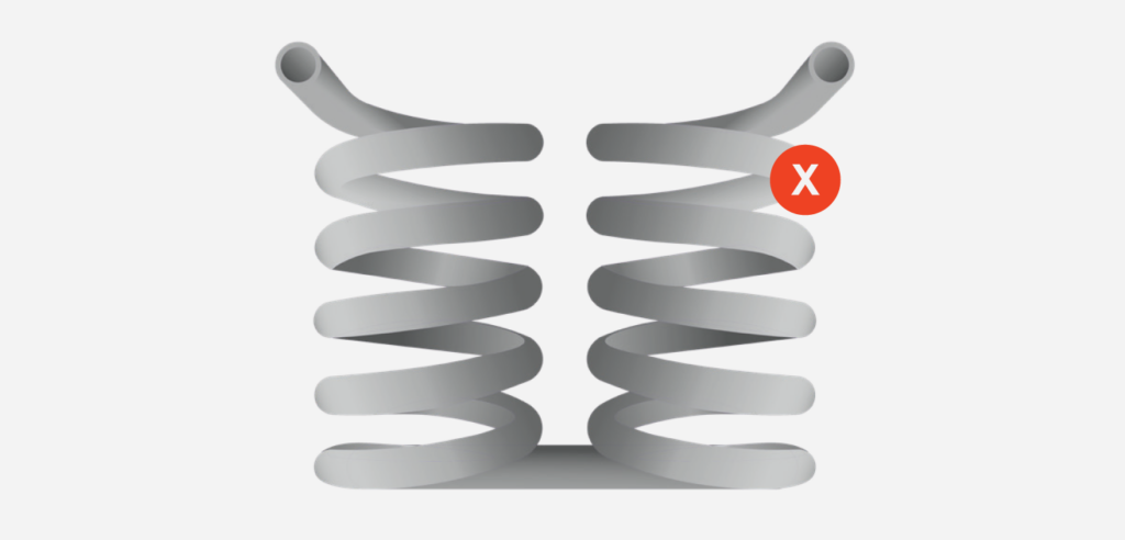
Mono-material packaging simplifies recycling but does come with challenges, such as finding plastic alternatives to metal springs and other traditional metal components. Manufacturers are also limited in design by choosing mono-material packaging because they can’t use decorative metal coatings.
A simple way to meet the demand for sustainable packaging without making consumers pay more for beauty products is by choosing a minimalist design (Figure 4). Sleek designs without added decorative features can reduce production complexity and material usage. The challenge to choosing minimalist designs is standing out in a market that relies so much on eye-catching products.
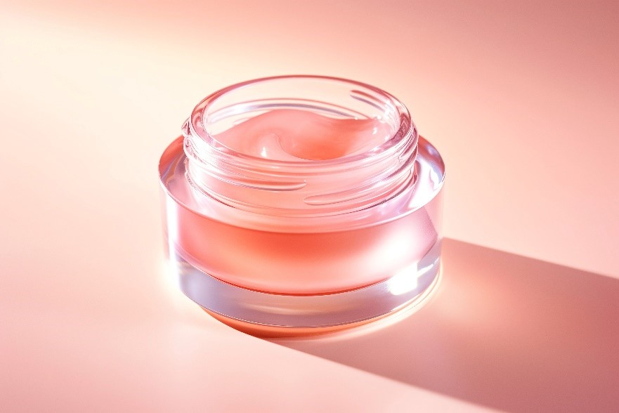
Figure 4. Minimalist designs can reduce material usage and simplify production
Design services help meet manufacturing challenges
Producing flawless cosmetic packaging with the luxe feel consumers expect using sustainable materials is a serious challenge. That’s where working with companies with design services and a range of manufacturing capabilities becomes essential. SyBridge experts can complete design for manufacturability (DFM) checks and simulation analysis to identify production issues before production begins, reducing design iterations and saving on production costs (Figure 4).
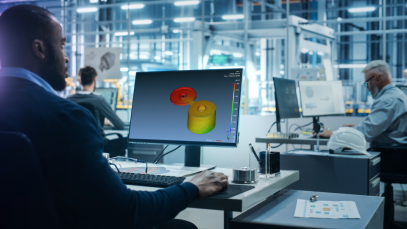
Figure 5. DFM checks help determine how to manufacture the highest-quality part at the lowest possible cost per unit.
Design services are essential not only for testing novel ideas but also for optimizing current production. SyBridge experts can use product data and analytic tools to create a digital thread — a centralized source of truth for the part. We use the digital thread to gain insights about a part’s lifecycle (design to final production) and see opportunities for increased efficiency and improved quality (Figure 5).
Novel dispensing methods make for more hygienic products
A carryover from the COVID-19 pandemic continuing to influence health and beauty products is an emphasis on hygiene. Where many skincare and makeup products require brushes or even a fingertip for application, consumers are now choosing contactless options like droppers, misters, products with internal applicators, and airless pumps.
Airless pumps reduce the chance of harmful bacteria getting into beauty products during use or illnesses spreading between people sharing the product (Figure 6). Pump dispensers also give customers precise control over how much product they use because each pump produces an exact volume. Companies can use pumps as an opportunity to provide instant brand recognition through contoured pump heads and other unique details.
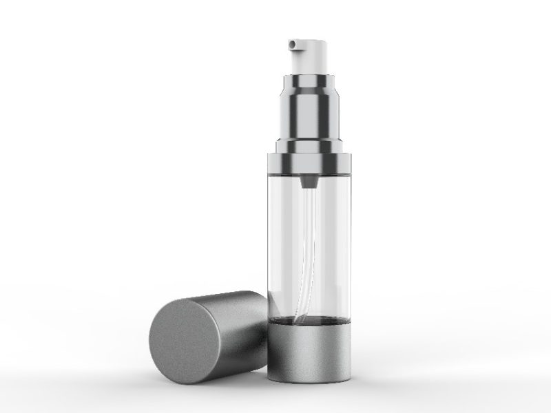
Figure 6. Airless pumps help reduce the spread of microbes and regulate dosing.
In addition to enhanced hygiene and dosing control, the airless packaging used in pumps and sprays can preserve the chemical composition of the formula by not introducing oxygen during use. This extends the product’s shelf life. Airless packaging can help reduce waste, and it is often made from mono-material, making it 100% recyclable.
Manufacturing for optimal user experience and safe shipping
A challenge for manufacturing novel dispensing methods is ensuring function. Consumers can easily become frustrated and dissatisfied when features such as pumps malfunction, ultimately costing brands the loyalty they have worked hard to gain. Precise manufacturing is essential to avoid warpages, stress cracks, and other flaws that can cause packaging to malfunction.
E-commerce companies selling cosmetics also need packaging that meets shipping standards. Products must have the strength to withstand rough handling during transportation, sortation, and distribution.
SyBridge helps companies manufacture uniform, strong products by incorporating quality inspection services and advanced designs, such as conformal cooling, in our manufacturing technology. Our precision manufacturing can help companies achieve high-feature, aesthetic parts that are also functional.
Partnering with SyBridge
Manufacturing partnerships help cosmetics companies maintain a competitive edge in the fast-paced industry. Since needs vary by product, partners with multiple capabilities are especially valuable and critical to support reduced overall tooling costs. SyBridge experts can help cosmetics packaging manufacturers wherever they are—whether seeing if a novel design is achievable or choosing the best manufacturing technology for a proven product.
Staying ahead of 2024 beauty trends is possible with the right partners. Connect with a SyBridge expert today to learn how our comprehensive services can help you meet your goals this year.
The post 2024 Trends in Cosmetic Packaging appeared first on SyBridge Technologies.
]]>The post 7 Common Injection Molding Defects and How to Avoid Them appeared first on SyBridge Technologies.
]]>Defects can reduce the speed and cost-efficiency of the entire product development process, and can potentially shorten product life spans if left unchecked. Injection molding issues and defects can be caused by a host of reasons, including poor design, production process mistakes, quality control failures, and more. As such, it’s important to take a proactive approach to risk mitigation throughout the product development process so as to reduce the chances of potential injection molding defects.
Here are a few of the most common defects that may occur in plastic injection molding — and how product teams can avoid them.
1. Flow Lines
Flow lines are off-color lines, streaks, and other patterns that appear on the surface of a part. These are caused by the shot of molten plastic moving at different speeds throughout the injection mold, which ultimately causes the resin to solidify at different rates. This is often a sign that injection speed and/or pressure are too low.
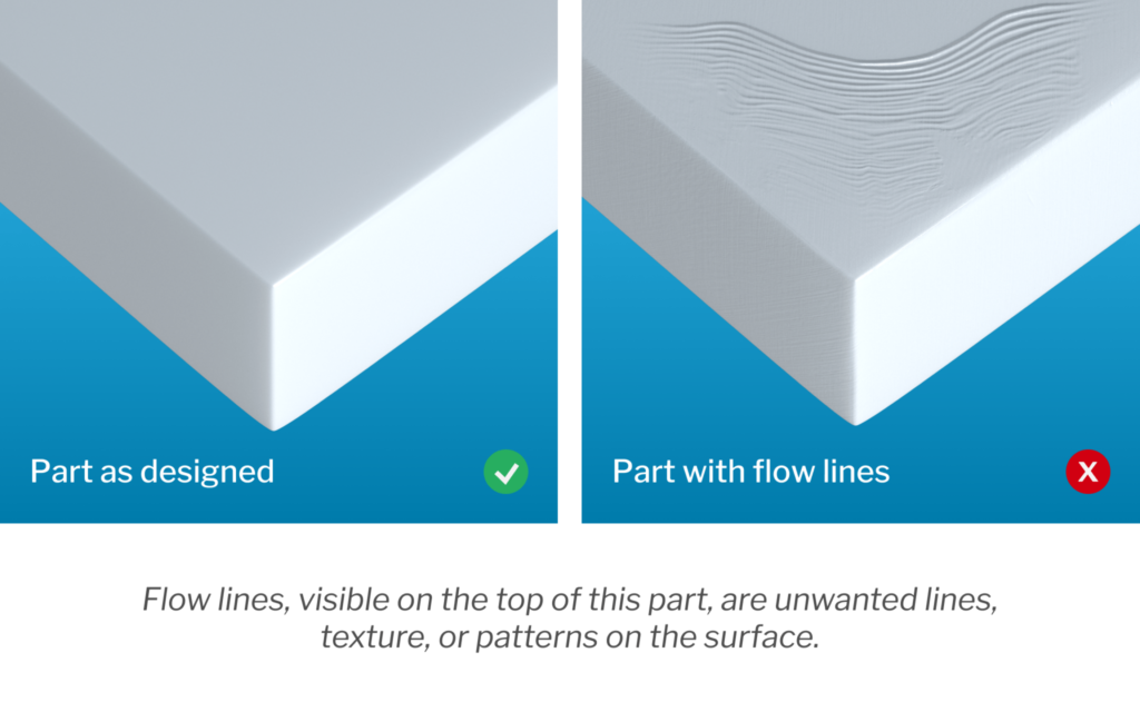
Flow lines can also appear when the thermoplastic resin moves through parts of the mold with different wall thicknesses — which is why maintaining consistent wall thickness or ensuring that chamfers and fillets are an appropriate length is critical. Placing the gate in a thin-walled section of the tool cavity can further help to reduce flow lines.
2. Sink Marks
Sink marks appear as depressions, dents, or craters in thick sections of a part. Thicker sections take longer to cool, which can have the often unanticipated side effect of the inner portions of the part shrinking and contracting at a much different rate than the outer sections.
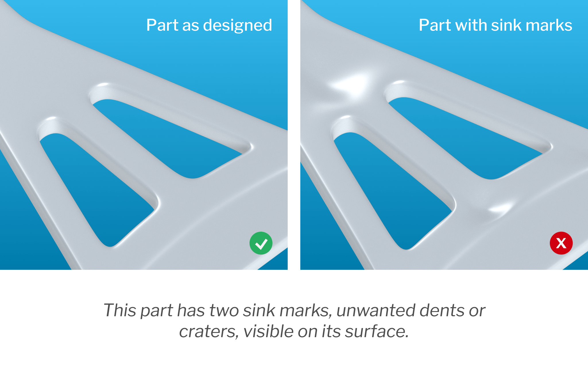
Though most often an indicator that the plastic needs more time inside the mold to properly cool and cure, sink marks may sometimes be remedied by reducing the thickness of the thickest wall sections, which helps to ensure more even and thorough cooling. Inadequate pressure in the mold cavity or higher-than-desirable temperatures at the gate can also contribute to the development of the defects.
On the design side, the risk of sink marks can be minimized by ensuring proper injection molding rib thickness and wall thickness. These actions can also help to increase the overall strength of the part.
3. Surface Delamination
What is delamination? Delamination is a condition that causes a part’s surface to separate into thin layers. These layers, which appear like coatings that can be peeled off, are caused by the presence of contaminants in the material that do not bond with the plastic, creating localized faults. An over-dependence on mold release agents can also cause delamination.
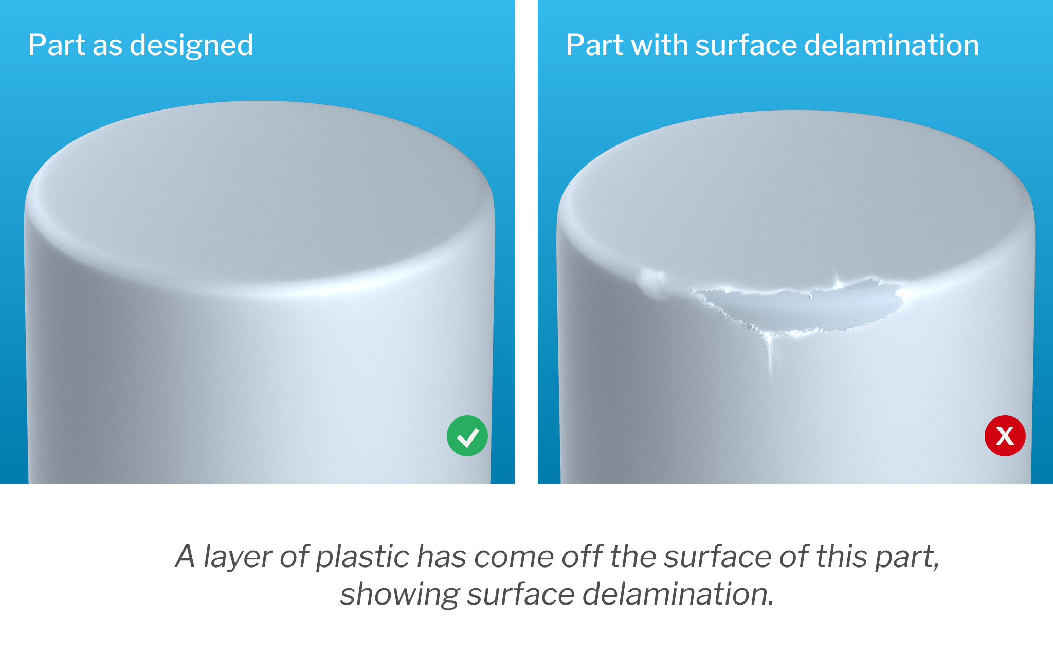
To encourage delamination repair and prevention, teams should increase mold temperatures and tailor the mold ejection mechanism to be less dependent on mold-release agents, since these agents can increase the risk of delamination. Properly pre-drying the plastic before molding can also help.
4. Weld Lines
Also called knit lines, these defects mark where two flows of molten resin came together as they moved through the mold geometry. This happens around any part of the geometry that has a hole. As the plastic flows and wraps around each side of a hole, the two flows of plastic meet. If the temperature of the flow isn’t just right, the two flows won’t properly bond together and will instead cause a visible weld line. This reduces the overall strength and durability of the component.
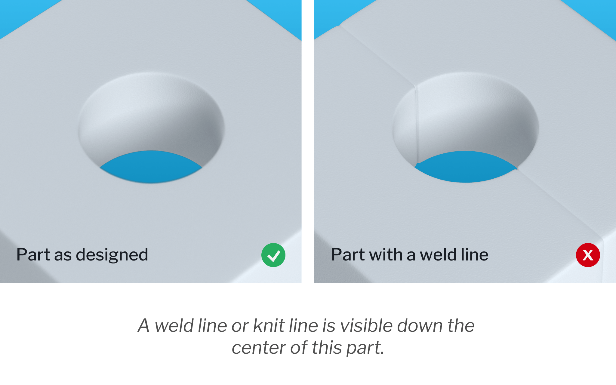
Raising the temperature of the molten resin can help to prevent the solidification process from beginning too soon, as can increasing injection speed and pressure. Resins with lower viscosity and lower melting points are less prone to developing weld lines in injection molding, which can also be eliminated by removing partitions from mold design.
5. Short Shots
“Short shots” refer to instances in which the resin doesn’t entirely fill the mold cavity, resulting in incomplete and unusable parts.

What causes short shots in injection molding? Typically, they are the result of restricted flow within the mold, which can be caused by gates that are too narrow or have become blocked, trapped air pockets, or insufficient injection pressure. Material viscosity and mold temperature are also contributors. Increasing mold temperature and incorporating additional venting into mold design to allow air to properly escape can help prevent the occurrence of short shots.
6. Warping
Injection molding warping refers to unintended twists or bends caused by uneven internal shrinkage during the cooling process. Warping defects in injection molding are generally the result of non-uniform or inconsistent mold cooling, which creates stresses within the material.
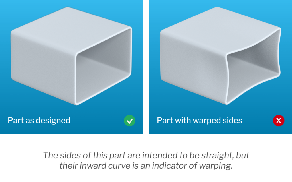
Preventing warpage defects in injection molding is a matter of guaranteeing that parts are given enough time to cool — and at a sufficiently gradual rate — to prevent internal stresses from forming and damaging the piece. Uniform wall thickness in mold design is crucial for many reasons, critical among them being that it helps ensure that the plastic flows through the mold cavity in a single direction.
It’s worth noting that materials with semi-crystalline structures are more likely to develop warping.
7. Jetting
Jetting defects in injection molding are another potential result of an uneven solidification process. Jetting occurs when an initial jet of resin enters the mold and has enough time to begin setting before the cavity fills. This creates visible, squiggly flow patterns on the piece’s surface and decreases the strength of the part.
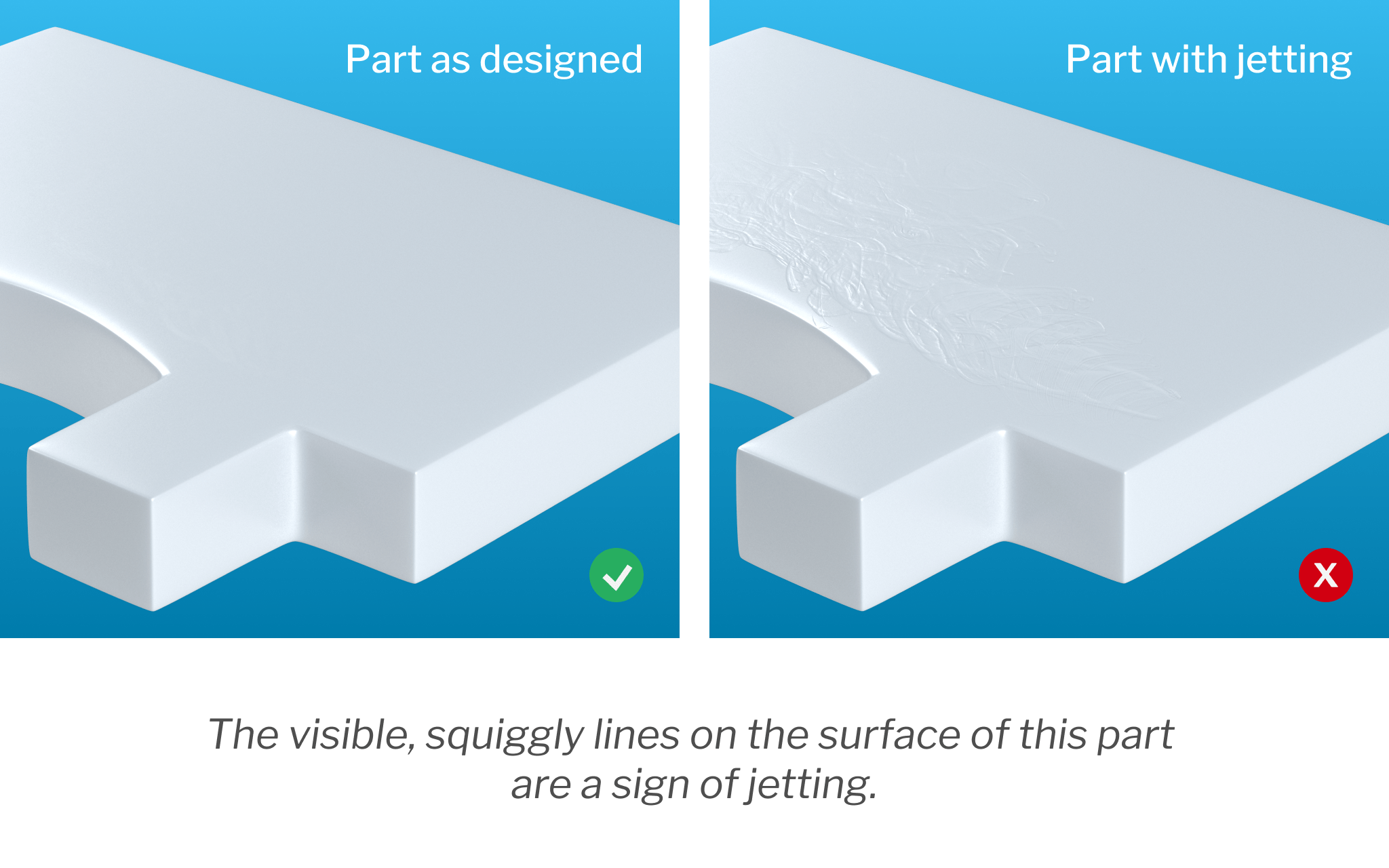
Reducing injection pressure is often the best way to ensure more gradual fills, but increasing the mold and resin temperature can also help to prevent any jets from preemptively setting. Placing the injection gate so that the flow of material runs through the shortest axis of the mold is another effective means of minimizing jetting.
Prevent Injection Molding Defects and Causes
Injection molding can be a highly efficient manufacturing method for producing highly repeatable plastic parts, but, as with many processes, producing high quality end-parts requires a high level of attention to detail and a proactive approach to risk management. Everyone involved in the product development process — from the initial design and proof-of-concept stages all the way to fulfillment — needs to do their due diligence to ensure products meet the highest quality standards and avoid these common plastic injection molding issues.
Choosing a manufacturing partner like SyBridge, who is well-versed in common defects in injection molding and their troubleshooting, can mean the difference between high-quality parts — produced on-time and within budget — and those marked with weld lines, jet, flash, sink marks, and other defects. In addition to being an experienced on-demand manufacturing shop, we also provide design consulting and optimization services that ensure we’re able to help every team create functional, elegant, high-performance parts as efficiently as possible. Contact us today to learn more about our injection molding services.
The post 7 Common Injection Molding Defects and How to Avoid Them appeared first on SyBridge Technologies.
]]>The post Critical Design Guidelines for Urethane Casting appeared first on SyBridge Technologies.
]]>The urethane casting build process involves first creating a master pattern — essentially a replica (often 3D printed) of the final part. The pattern is then fully encased in liquid silicone and allowed to cure. The mold is cut into halves and the pattern removed. From there, the process can be repeated using the proper urethane casting resin.
Polyurethane casting materials are capable of providing performance characteristics comparable — if not superior — to the thermoplastics used in injection molding. However, as with other production methods, the process of casting high-quality parts that meet all performance requirements also requires that product teams follow design for manufacturability (DFM) best practices. Here are some of the most important guidelines for product teams to keep in mind:
Tolerances
Some degree of variation is inevitable in manufacturing (though teams should endeavor to account for as many of the variables as possible), and tolerances are the acceptable amount of dimensional variation between individual units. Cast urethane tolerances are typically around ± 0.015” or ± 0.003 per inch, whichever is greater. Tighter tolerances may be offered on a case-by-case basis.
In general, a shrinkage rate of +0.15% is typical. This is caused by the thermal expansion of the urethane casting material and how the flexible silicone mold warms in response.
Additionally, it’s important to note that while urethane cast parts take well to post-processing (though additional processes, such as polishing or custom finishing, can quickly drive up production costs), some design features like sharp corners or lettering may experience slight rounding in the cooling process, impacting the definition of finer details. That said, it is possible to add a finish to the master pattern that mimics an SPI finish or texture. You can also paint urethane cast parts to match Pantone colors, and certain color and pigments can be added directly to the casting materials, as well.
Wall Thickness
Parts produced with urethane casting should have a minimum wall thickness of 0.040” (1mm), though walls as thin as 0.020” (0.5mm) can be achieved for some small components. Larger parts generally require thicker walls in order to ensure the piece’s structural integrity.
Urethane casting does allow for parts with varying wall thicknesses or irregular geometries, but designing parts as such should be done only when strictly necessary. Maintaining a consistent thickness helps to minimize the potential for improper shrinkage and deformation during the curing process.
Undercuts and Draft
While undercuts can quickly complicate injection molding design, the flexible nature of the silicone molds used in urethane casting typically allows for parts to be removed easily and without damage.
The same is true for draft angles: they are a necessity for ejecting pieces from metal molds, but less essential for urethane-cast parts. That said, incorporating 3-5 degrees of draft into part design can significantly reduce strain on your mold and extend its life cycle.
Ribs
Ribs add stability and strength, but it’s important to ensure that they are oriented so as to maximize the bending stiffness of the walls they support. As a general rule of thumb, the rib’s height should be no more than three times its width, and the width of the rib where it meets the part wall should be between 40-60% of the wall thickness. Lastly, to maximize the strength of the rib, all interior corners should have a fillet radius of at least 25% of the part’s wall thickness.
Bosses
Bosses allow secure mating parts to be attached through the use of screws, pins, and other fasteners. As with ribs, the base radius should be about 25% of the part’s wall thickness, which has the added benefit in this case of helping to prevent the fastener from burning when it’s set into the boss.
Interior boss corners should use a 0.060” (1.5mm) fillet radius to minimize thickness and reduce the likelihood of sinks developing. Ensuring that bosses are no more than 60% of the nominal wall thickness also helps to minimize shrinkage.
Leverage the Benefits of Urethane Casting Today
The advantages of urethane casting — short lead times, low cost, and design and material flexibility, to name a few — only truly pay off if you adhere to design and manufacturing best practices. This means paying attention to variables like urethane casting material properties, general tolerances for rubber parts, and everything in between — which quickly becomes complicated without the assistance of an experienced manufacturing partner.
With our agile approach, we’re able to significantly shorten lead times and increase operational efficiency for product teams of all shapes and sizes. And at SyBridge, our business isn’t just based on manufacturing superior parts — we also work tirelessly to make sure that our production processes are as efficient as possible, even if that means using a combination of techniques to get the job done. Contact us today to learn more.
The post Critical Design Guidelines for Urethane Casting appeared first on SyBridge Technologies.
]]>The post The Ultimate CNC Design for Manufacturability (DFM) Checklist appeared first on SyBridge Technologies.
]]>In this downloadable guide, we’ve compiled eight common DFM considerations that should remain top-of-mind when designing parts for CNC machining. You can save significant time and cost by checking your design against this list before submitting it for manufacturing.
Top 8 Design for Manufacturing Considerations for CNC Machining
1. Are there any deep pockets in the design?
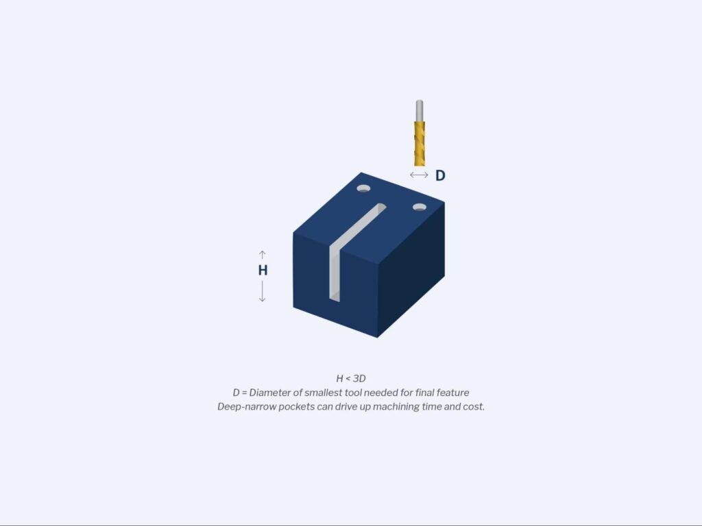
Deep-narrow pockets or slots must be machined by longer tools, and longer tools are more prone to breakage, and can also cause chatter, or machine vibrations. Additionally, it takes several passes to machine a deep pocket, which drives up machining time and manufacturing costs.
Avoid designing parts with deep pockets whenever possible. If a deep pocket cannot be avoided, engineers and designers should decrease its depth as much as possible or increase the cross-section area of the pocket. As a rule, pocket depth shouldn’t exceed 3x the diameter of the tool being used to make it. For example, pockets should be no deeper than 1.5” when using a 0.5” cutter. Engineers may have to adjust this figure based on the material they are using and the tools that are available to them.
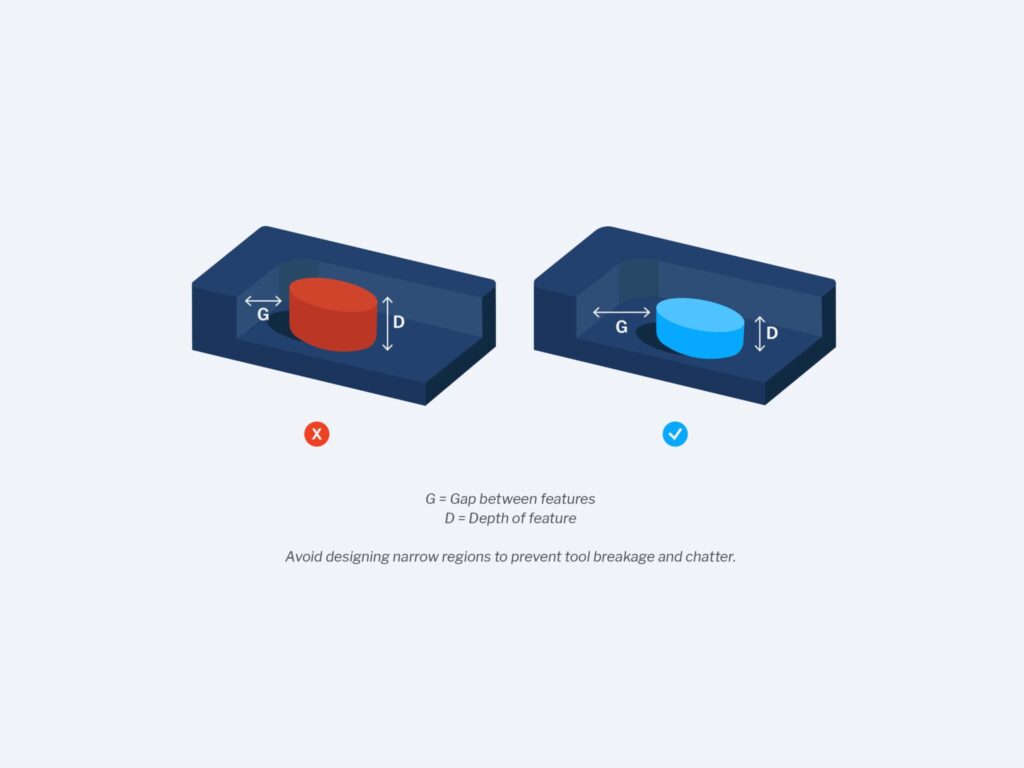
2. Are there any narrow regions?
Narrow regions are difficult to manufacture because the size of the cutter is restricted by the smallest distance between the various faces of the feature. Long and small diameter cutters are prone to breakage and chatter.
Avoid designing features or faces that are too narrow for a cutter to easily pass through. If narrow regions cannot be avoided, however, they must not be too deep. Remember that the depth of any feature should be less than 3x the diameter of the tool. As a best practice, wall sections should be greater than 0.01 inches thick. A shorter cutter with a larger diameter can also be employed to reduce chatter.
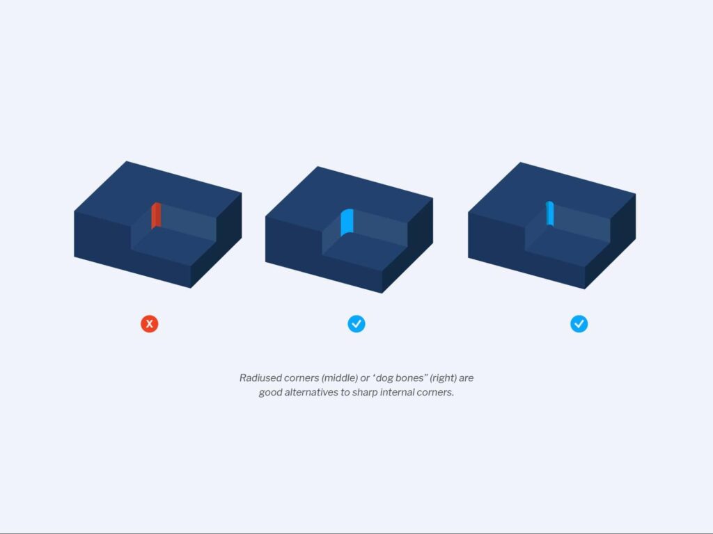
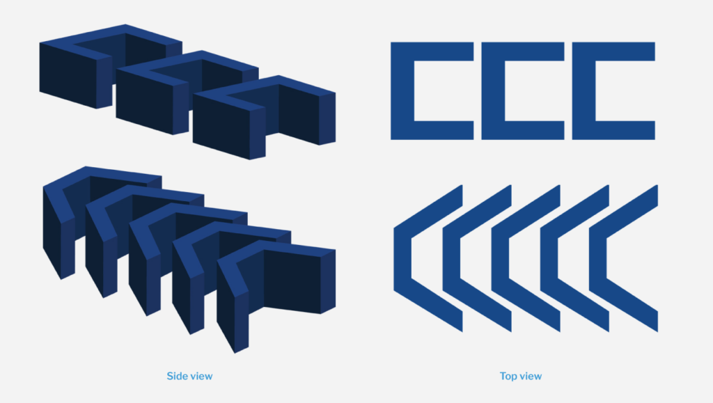
3. Are there any sharp internal corners?
Since all CNC drill bits are circular, it’s difficult to achieve sharp internal corners. Instead, the drill bit will leave behind a pocket of unmachined space called an internal corner radius. It’s possible to machine sharp internal corners using workarounds, like electrical discharge machining, but these methods tend to be expensive.
Avoid sharp inside corners whenever possible. Ideally, a corner radius needs to be slightly larger than the cutter. If a corner radius is the same diameter as the cutter being used to form it, it can cause chatter and premature tool wear.
Increasing the corner radii beyond the standard value by as little as 0.005” can give the tool enough room to move around and follow a more circular path.
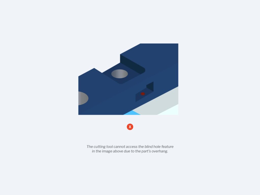
4. Are there any inaccessible features?
Inaccessible features like counterbores that open inside another pocket or pockets with negative drafts take longer to machine— if they’re even possible — because the cutting tool cannot easily access them, which in turn drives up costs.
You should ensure a cutting tool has full access to all features within a part without being blocked by another feature.
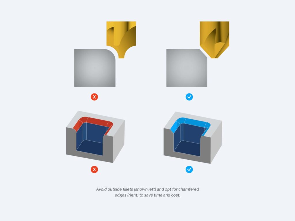
5. Are there any outside fillets?
Outside fillets, or fillets on the top edges of pockets, bosses, and slots, require an exceptionally sharp cutter and a precise setup. Both of these requirements can be prohibitively expensive for some product teams. To avoid incurring these costs, bevel or chamfer — rather than fillet — the outside edges of features.
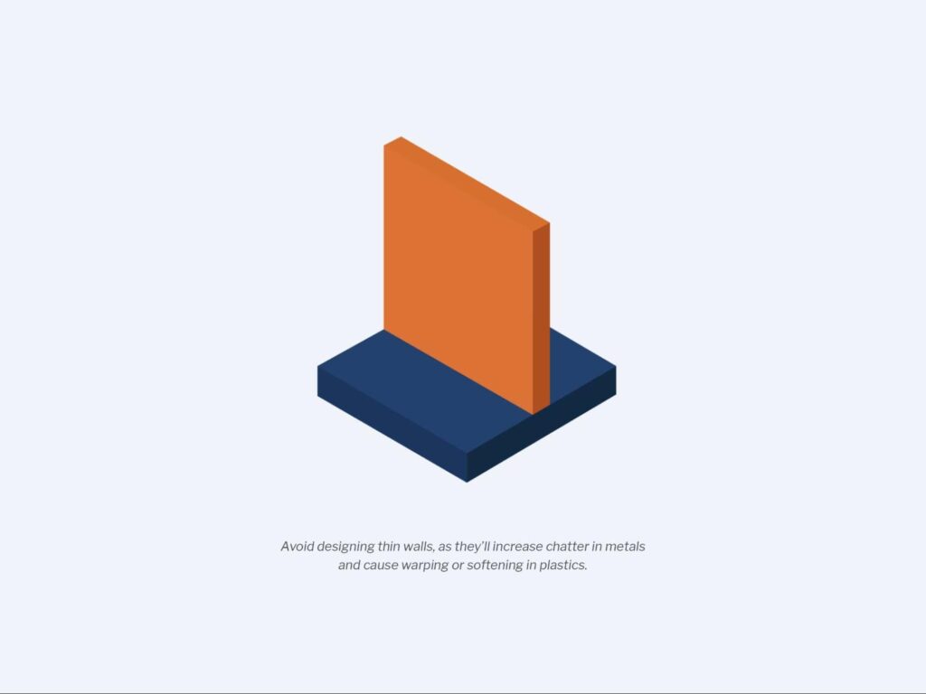
6. Are the part’s walls too thin?
When it comes to CNC machining with metal, thin walls increase chatter, which can compromise the accuracy of the machining process and the surface finish of the part. With plastics, thin walls can cause warping and softening. As such, you should do your best to avoid designing parts with thin walls.
The ideal minimum wall thickness for metals is 0.8 mm for metals and 1.5 mm for plastics. You may be able to achieve thinner sections without significant risk, but this needs to be assessed on a case by case basis.
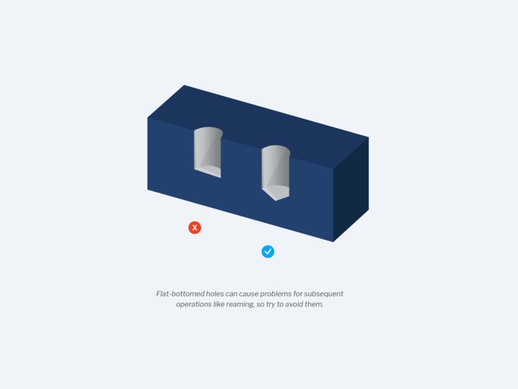
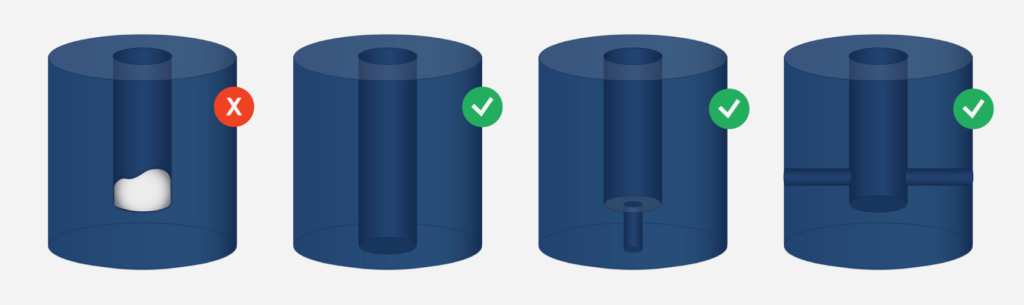
7. Are there any flat-bottomed holes?
Flat-bottomed holes require advanced machining operations and often cause problems down the line for subsequent operations like reaming. Avoid creating blind holes with a flat bottom — especially small holes — and instead use a standard twist drill to create holes with cone-shaped bottoms. Cone angles are commonly 118° or 135°.
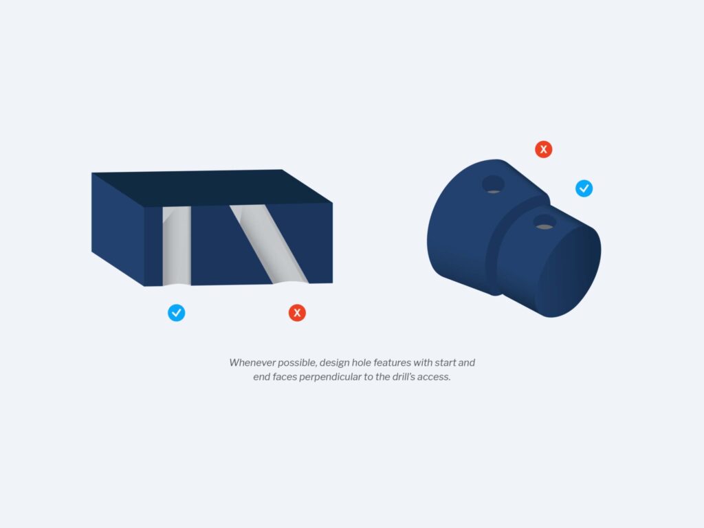
8. Can the CNC machine’s drills enter and exit easily?
A drill tip will wander when it comes into contact with the material’s surface if that surface isn’t perpendicular to the drill axis. Also, uneven exit burrs around the exit hole will make removing the burr difficult. To ease entry and exit, avoid designing hole features with start and end faces that are not perpendicular to the drill’s axis.
Recap of All 8 Design Considerations for CNC Machining
- Avoid designing parts with deep pockets whenever possible because deep-narrow pockets can drive up machining time and cost.
- Avoid designing features or faces that are too narrow for a cutter to easily pass through to prevent tool breakage and chatter.
- Radiused corners (middle) or “dog bones” (right) are good alternatives to sharp internal corners.
- Ensure a cutting tool has full access to all features within a part without being blocked by another feature
- Avoid outside fillets (shown left) and opt for chamfered edges (right) to save time and cost.
- Avoid designing thin walls, as they’ll increase chatter in metals and cause warping or softening in plastics.
- Avoid Flat-bottomed holes that can cause problems for subsequent operations like reaming.
- Whenever possible, design hole features with start and end faces perpendicular to the drill’s access.
Get Started With a DFM Expert
Designing for manufacturability accelerates the CNC machining process, reduces operating costs, elevates energy efficiency, and helps product teams create clean, functional parts. Refer to this short checklist often to make sure your designs are on the right track, but an experienced manufacturing partner like SyBridge can offer more nuanced insights.
The SyBridge team can help engineers, designers, and product teams ensure they don’t miss the mark when it comes to DFM. We have access to the latest digital design technologies available so our partners can take their designs to the next level, while we provide expert advice on manufacturability and part quality. What’s more, our experts are prepared to assist customers with design and prototyping for a range of manufacturing methods — from CNC machining and injection molding to urethane casting and 3D printing. Let’s create something incredible. Contact us today.
The post The Ultimate CNC Design for Manufacturability (DFM) Checklist appeared first on SyBridge Technologies.
]]>The post HP Multi Jet Fusion Design Guidelines appeared first on SyBridge Technologies.
]]>Multi Jet Fusion enables the efficient production of end-use nylon parts using additive technologies. Here’s a checklist for design teams.
Introduction
What is Multi Jet Fusion?
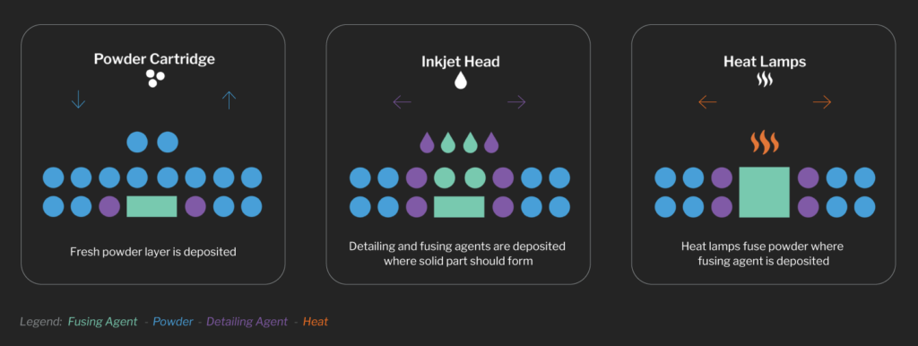
Multi Jet Fusion (MJF) is an industrial form of 3D printing that can be used to produce functional nylon prototypes to higher volume production parts with exceptional design freedom and mechanical properties. The MJF process works by using inkjet nozzles to selectively distribute fusing and detailing agents across a bed layered with nylon powder. Unlike selective laser sintering, which uses lasers to fuse the powder into solid material, the MJF printer uses a continuous sweeping motion to distribute agents and apply heat across the print bed layer by layer until the part is finished, MJF can produce high-quality parts at high speeds.
This manufacturing process also does not require support structures to produce parts, making it possible to create complex geometries like internal channels or co-printed assemblies. MJF parts have mechanical properties comparable to injection-molded ones, but without the need for expensive tooling.
Designing for manufacturability will go a long way in ensuring optimal part quality and yield, minimizing post-processing needs, and driving cost reductions. Here’s a quick checklist to help your team ensure that you’re following MJF design best practices.
1. Is MJF a suitable process for my project?
Before diving into design changes, it is important to ensure that the MJF process will meet all product requirements. Here are a few questions to ask yourself:
Do any of the material offerings meet my product requirements?
While MJF has many strengths, it has a limited list of approved materials. PA12 and its glass bead counterpart are fairly versatile for rigid plastic applications. TPU, a flexible polyamide, can find use where an elastomeric material is required. If the available materials do not meet a specific requirement, you may need to consider a different process.
Does my part fit in the build volume?
One key limiting factor is the machine’s build volume, which is 380 x 380 x 284mm for the Jet Fusion 4200. In some cases, large parts can be printed as smaller subcomponents and assembled using adhesive or mechanical joints. In this case, design features such as dovetail joints may facilitate alignment and adhesion.
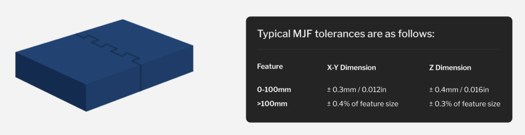
Do I have any tight tolerances I need to hit?
While the gap between additive and injection molding tolerances is narrowing, it is important to make sure that MJF’s tolerances are sufficient within the context of your assembly.
2. Are there areas where I can use less material?
In most cases, MJF defects are caused by thermal gradients that develop during the build. If the material cools unevenly, the piece may warp or develop sinks. Parts that are long and thin, have abrupt changes in cross-sections, or have thin curved surfaces are especially prone to shrink-induced warp.
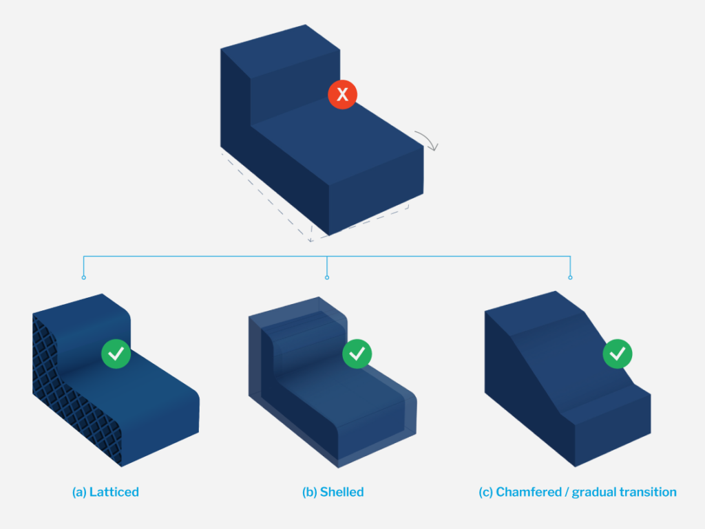
Removing material from part designs wherever possible through the use of pockets, shelling, lattices, and topology optimization is key to mitigating and preventing these defects. Avoiding large changes in cross-sections is another way to limit warp. Ensure that chamfers and fillets are incorporated where needed throughout the part design to make the transitions between different features more gradual.
3. Are my features above the minimum threshold size?
In general, the wall thickness of MJF-printed parts should be a minimum of 1.5mm. Small design features should also be no smaller than 1.5mm, though some features such as slits, embossing, engraving, or the diameters of holes and shafts can be as small as 0.5mm. For embossed or debossed text, the font should be no smaller than 6pt (approximately 2mm) and should be a minimum of 0.3mm deep.
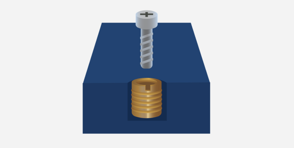
If a part includes screw threads, they should be M6 or larger. Where smaller, more precise, or more durable threads are needed, consider using threaded inserts. Beyond feature resolution, you should also consider how small, slender features might break off in post-processing.
4. Have I taken assembly tolerances into account?
Even with the greater geometric flexibility provided by the MJF process, some applications may still require a part to be assembled from multiple components. In general, mating faces should have 0.4 – 0.6mm of clearance to ensure that the components can properly fit.
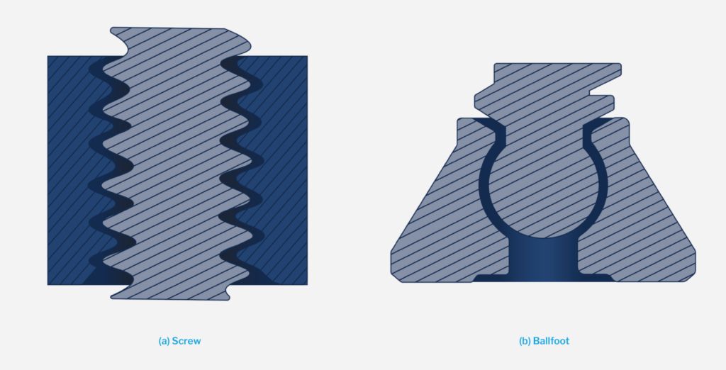
clearance to prevent fusing due to higher contact surface-area
If your project involves co-printing assemblies, the components printed together should have at least 0.5mm of clearance, but may require more, particularly when there are thick cross sections or there is a significant contact surface area.
5. Is my part design optimized for post-processing?
If your part requires post-processing, there are a few things to double-check in your design to help make secondary operations more effective.
- Ensure that there are no unvented or trapped volumes in the design.
- Avoid blind holes whenever possible — these are hard to clean, which can quickly drive up costs.
- Add fillets to corners where the powder can cake and become difficult to remove through standard tumbling and bead blasting.

6. Have I seized every opportunity to lower part costs?
Besides improving part quality, intelligent DFM changes can drive cost savings. Lightweighting your part, for example, reduces the risk of defects and lowers the material cost per part. The other main consideration when designing for MJF and cost is optimizing nestability in a build. Adding draft or altering the position of printed assemblies may increase the number of parts that can fit per build and distribute fixed costs over more parts, lowering the overall part cost.
In this example, adding draft enables packing of two additional parts.
In addition to optimizing designs for manufacturability, additional factors to consider include your part’s cosmetics, surface finish, and ease of storage and transportation. MJF parts are naturally grey, but can be dyed black easily. If painting, priming, or other processes are not essential to the part’s function, they can be foregone to reduce expenses. Most MJF-printed parts will have a 125-250 microinches RA finish — if a smoother surface is needed, the part can undergo a variety of surface treatments, including sanding, tumbling, or vapor smoothing. Texturing can be an effective design technique to improve part aesthetics without additional post-processing.
Getting Started With a DFM Expert
Adhering to DFM principles is key to the success of manufacturing processes for a number of reasons. It helps to keep your operating expenses as low as possible, allows you to detect and address design issues early, and improves your overall part quality. This checklist is a valuable resource for making sure your MJF parts are optimized and refined before production begins.
The added advantage of partnering with SyBridge is that your team gains access to the latest in digital design technologies and expert advice. Our team is standing by to help guide each project from design and prototyping through to fulfillment, ensuring that you receive superior-quality parts on time and at the right price. Contact us today to get started.
The post HP Multi Jet Fusion Design Guidelines appeared first on SyBridge Technologies.
]]>The post Thermoplastics vs. Thermosets: What’s the Difference? appeared first on SyBridge Technologies.
]]>When designing a part, it’s important to understand critical differences between comparable materials. For instance, substituting a thermoplastic instead of a thermoset to create a product that’s meant to withstand high temperatures would have disastrous results.
The terms “thermoplastic” and “thermoset” appear in many of the same conversations regarding plastic part manufacturing, but they’re not interchangeable. This article breaks down the major differences between thermoplastics and thermosets, as well as key advantages and best applications for each material.
Thermoplastics: What You Need to Know
Mechanical/Chemical Properties
A thermoplastic is any plastic material with a melting point that becomes molten when heated, solid when cooled, and can be re-melted or molded after cooling. The process is completely reversible, and doing so will not significantly compromise the material’s physical integrity.
Thermoplastics are usually stored as pellets to facilitate easy melting during the injection molding process. Common examples of thermoplastics include acrylic, polyester, nylon, and PVC.
- Nylon: Nylon provides a unique combination of strength and wear resistance that makes this family of materials well-suited for a range of applications.
- TPE and TPU: When product designers and engineers want a part to have certain properties like shock absorption, flex rebound, or high impact strength, they often turn to polymers made out of thermoplastic elastomers.
- ULTEM (PEI): ULTEM® is one of the only resins approved for use in aerospace settings. It is also among the most versatile plastics on the market.
Advantages of Thermoplastics
Thermoplastics are strong, shrink-resistant, and relatively easy to use. Their inherent flexibility makes them an excellent choice for manufacturers who require shock-absorbent products that can withstand wear and tear while retaining their shape.
Thermoplastics are generally more cost-effective than thermosets because they’re easier to process. This is because thermoplastics are made in higher volumes and don’t require post-processing. Plus, thermoplastic molds can be made from affordable materials like aluminum. Thermoplastics are highly compatible with injection molding processes, and are ideal for making repeatable parts in high volumes.
Additionally, thermoplastics are some of the more environmentally friendly plastics on the market as they are highly recyclable by design. As an added benefit, manufacturing with thermoplastics produces fewer toxic fumes than working with thermosets.
Common Thermoplastics Applications
Manufacturers often use thermoplastics for prototyping because if the final product doesn’t meet certain standards, they can easily melt the part down and start over without producing a lot of scrap material.

Beyond part prototyping, thermoplastics can be used to create a range of familiar consumer products, as well as medical devices, automotive components, and more.
Thermosets: What You Need to Know
Mechanical/Chemical Properties
In contrast to thermoplastics, a thermoset is any plastic material that hardens once cured by heat and cannot be reshaped after the curing process. During curing, valence bonds in the polymer cross-link together to form three-dimensional chemical bonds that cannot be undone, even under extreme heat.
Thermosets are usually stored in liquid form in large containers. Common examples of thermosets include epoxy, silicone, and polyurethane.
- Epoxy (EPX 82): An additive material developed by Carbon for its DLS process. This material is ideal for automotive, industrial, and consumer applications.
- Silicone (SIL 30): SIL 30 is an additive material developed by Carbon® for its digital light synthesis (DLS). Also known as SIL 30, this silicone urethane offers a unique combination of biocompatibility.
- RPU 70: Known for its toughness, strength, and ability to withstand heat, RPU can be used across multiple industries including consumer products, automotive, and industrial.
Others like Phenolics are available as a granular product.
Advantages of Thermosets
Thermosets offer a wide range of benefits; overall, they are strong, stable, chemical-resistant, and have outstanding electrical properties. They won’t warp, degrade, or break down easily in extreme temperatures.
Due to their strength and durability, thermosets are often used to reinforce another material’s structural properties. Among the most impact-resistant materials on the market, they are frequently used to seal products to protect them against deformation.
Common Thermosets Applications
While thermoplastics offer a more diverse range of high and low functionality applications, thermosets can be used to create high-performance products in a wide variety of industries.
Thermosets are ideal for building anything that comes into contact with extreme temperatures on a regular basis, such as kitchen appliances and electronics components.
Start Building With Us
The crucial difference between thermoplastics and thermosets boils down to how they react to heat. Thermoplastics can be molded and remolded in the presence of heat without losing structural integrity, while thermosets can be molded only once. Of the two, thermoplastics are better suited for all-purpose products that need to be strong and flexible, while thermosets make better high-performance products. An experienced manufacturing partner can help you decide which material best fits your needs.
When you partner with SyBridge, you partner with a dedicated team of engineers and manufacturing experts who will help you take your project to the next level. We’ll match your vision with optimal materials, manufacturing processes, and post-production services to ensure that you end up with a product of unmatched quality. Contact us today for a quote.
The post Thermoplastics vs. Thermosets: What’s the Difference? appeared first on SyBridge Technologies.
]]>The post Conformal Cooling: Higher-Quality Parts, Faster Injection Molding Cycle Times appeared first on SyBridge Technologies.
]]>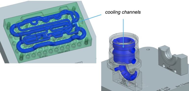
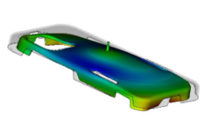
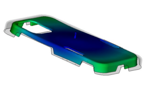
Reduced Risk of Part Warpage
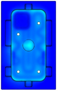
During the molding process a part cools from the exterior surface to the inner core of the plastic, ideally at the same rate for all areas of the part when it is designed with consistent wall thickness. When injection molding simple, uniform parts conventional cooling typically doesn’t pose any challenges, as all areas of the part generally cool at a similar rate.
However, if a part design is geometrically complex, then the part may not cool at an even rate in all areas, resulting in potential warpage or longer cooling cycles to ensure solidified parts before ejection. The truth is that in today’s world with increasingly complex part geometries, perfectly uniform cooling rates are difficult to attain. In the case of low volume runs, the inefficiencies of having a slightly longer cooling cycles can be negligible and tolerable for molders. However, in the case of high volume runs, these efficiencies can be opportunities to improve productivity or reduce waste. The resulting efficiency of conformal cooling depends on many factors, from the design of the cooling channels, the design of the part, the mold design and even the molding recipe. When done properly, conformal cooling solutions can improve tooling output by 50% or more.
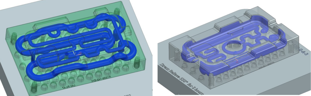
Conventional Cooling
Conformal Cooling
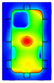
Including conformal cooling channels in the mold tooling will help address hot spots that result in warpage, resulting in better quality parts with less material waste and fewer defects.
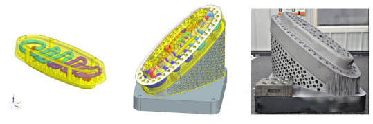
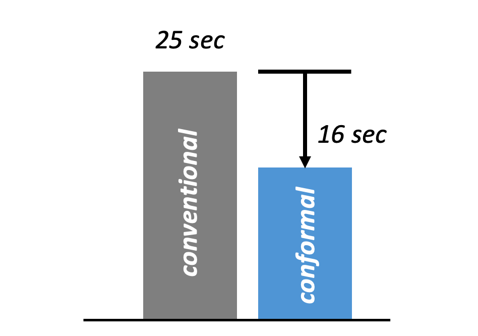
Faster Cycle Times
In addition to achieving a better quality end result with a lower risk of defects, conformal cooling channels often significantly decrease mold cycle times. In the example below, conformal cooling was used to reduce the cycle time of this high-volume plastic component by almost 40%, increasing mold productivity by nearly 50%.
Is Conformal Cooling Right for Your Needs?
Including conformal cooling channels in injection mold tooling is popular across industries and product types, particularly in the life sciences, and consumer products sectors where parts with complex geometries or high mold volumes are common. If you plan to produce a large volume of parts via injection molding and are concerned about warpage, designing your injection mold tooling with conformal cooling may be the right solution to help with cycle times and lower part costs. In order to ensure that the channels are properly designed for your part’s geometry and specific application, it is imperative to work with an experienced tooling designer who is knowledgeable about how to integrate these novel approaches into high precision tooling.
At SyBridge, our engineers are experts in the injection molding and tooling design processes, and have worked with companies across diverse industries to help them achieve incredible results when it comes to improving mold productivity, reducing defects, and producing higher-performing parts. Whether you already have a mold design that you believe would benefit from the addition of conformal cooling channels or you’re working on the design for a new part or product, our team is here to help.
Contact us to speak with an injection mold tooling design expert and discover if conformal cooling is right for your injection mold tooling needs.
The post Conformal Cooling: Higher-Quality Parts, Faster Injection Molding Cycle Times appeared first on SyBridge Technologies.
]]>The post What’s Next for Additive Manufacturing? appeared first on SyBridge Technologies.
]]>Today, 3D printing technologies continue to improve and engineers are constantly discovering new applications where additive manufacturing is more practical than producing parts via traditional technologies. In fact, additive manufacturing has evolved well beyond technologies principally suitable for prototyping to include production-grade technologies like Carbon® Digital Light Synthesis™ (DLS) and HP Multi Jet Fusion (MJF), which are capable of generating quality, functional end-use parts suitable for the most demanding applications. As the industry grows and gains further popularity, more companies will innovate and push the bounds of what additive manufacturing is capable of. With these advancements, new ideas will come to light and open up even more possibilities for industrial-grade 3D printing.
The Rise of Additive Manufacturing
In the early 2010s, 3D printing slid into the mainstream and has since truly taken off. Much of the recent growth can be attributed to the fact that automotive, consumer goods, aerospace, and medical device companies have opened their eyes to the many benefits of additive manufacturing. Not only can companies use additive technologies to quickly create prototypes, but they can also produce everything from aircraft maintenance tools to accurate surgical models and functional automotive parts.
With constantly improving material selections and advancements in print speed and accuracy, additive manufacturing has become a feasible production method for volume in the tens of thousands of parts. Companies are now able to cost-effectively produce custom products, such as helmets, hearing aids, prosthetics, and surgical guides on a mass scale. Manufacturers can make adjustments directly to a 3D CAD file and start production on a new part revision immediately, oftentimes weeks or months faster than it can take to manually adjust tooling for injection molding, the common alternative to 3D printing. Since there’s no need for expensive tooling, companies can keep production costs low, even as they change their design.
Bridge to Scalable Production
Regardless of the advantages of additive manufacturing, injection molding is still the gold standard for volume production of plastic parts, as it’s a tried and true scalable production method with a vast array of available materials. However, additive manufacturing has established its place alongside and in conjunction with injection molding as a bridge to production, allowing companies to receive their initial run of parts while the final injection mold tooling is being created. Through leveraging both the speed of additive manufacturing and the scalability of injection molding, companies are able to shorten product development timelines and gain a competitive advantage by getting to market quickly.
Along these lines, some companies have even started 3D printing injection mold tooling, as it’s a fraction of the cost of machined aluminum or steel tooling. Additionally, 3D printed tooling can be made quickly — it takes just two to three days to create tooling via additive manufacturing, while CNC machined steel tooling can take up to five months. Though 3D printed tooling is not nearly as durable as aluminum or steel tooling, it’s far more affordable for low-volume production runs if a desired material isn’t available to use with additive technologies.
But why do traditional injection molds take so long to manufacture? Machined molds will often have to go through additional post-processing steps using wire electrical-discharge machining (EDM) to achieve small details like sharp corners that are not achievable via CNC machining directly. However, these complex features can be printed directly with additive manufacturing, which can save time and money in the long run and makes 3D printing an ideal way to get a part into production quickly, even if steel or aluminum tooling is better-suited at scale.
With Supply Chain Woes, Additive Grows
Though additive manufacturing was already on the rise in the lead-up to 2020, it became increasingly important during the COVID-19 pandemic. Before the lockdowns and supply chain issues, companies could produce parts using conventional methods like injection molding and CNC machining in factories around the world before shipping them to warehouses and distribution centers. But suddenly, manufacturing techniques that had worked for decades weren’t quite cutting it in the midst of supply chain chaos. As a result, many companies turned to additive manufacturing to solve their supply chain woes.
Through distributed manufacturing networks, a rise in on-demand manufacturing services, and advancements in additive technologies and materials, more businesses turned to 3D printing instead of traditional technologies to produce small- and mid-sized production runs. And instead of shipping parts around the world, companies began to realize the ease and advantages of uploading CAD files to network-connected 3D printers that would then produce the parts closer to where they were needed. In addition to the increased design agility this afforded, along with reductions in logistics timelines and expenses, manufacturers were able to meet the booming demand for parts and products throughout the pandemic, including for essential products like medical equipment, face shields, and respirator components that were suffering extreme supply shortages.
The Future of Additive Manufacturing
As 2020, 2021, and 2022 have proven, 3D printing is a suitable manufacturing method for any industry looking for a rapid, adaptable production solution, no matter where they are in the world.
While supply chain issues have begun to ease, many companies have integrated 3D printing into their design and production processes, and are seeing it as the new normal when it comes to manufacturing geometrically-complex parts or even simpler parts at low to mid-size production volumes. And as a result of businesses’ continued reliance on additive manufacturing, new processes with greater speed, precision, and reliability coupled with robust and expansive material choices will continue to be developed in the coming years. These new additive manufacturing trends and developments will help 3D printing gain an even stronger foothold in the manufacturing world.
Adoption of Additive Manufacturing in Electric Vehicle Production
One area specifically where 3D printing will likely continue to carve out its niche is in the electric vehicle (EV) industry. Over the past few years, EVs have hit the mainstream, and they’re only continuing to grow in popularity. General Motors will phase out gas-powered cars by 2035 and President Biden plans to replace the federal fleet with EVs, so it’s clear that electric vehicles are here to stay. As manufacturers try to make EVs increasingly affordable and high-performing, they’ll look for cheaper, lighter, and more easily sourced parts, which will pave the way for more widespread adoption of additive manufacturing processes across the mobility industry. As quicker, more efficient product development cycles push the limits of traditional manufacturing technologies, this will create a whitespace for additive manufacturing due to the speed and design flexibility it affords.
Decentralized 3D Printing of Customizable Parts at Scale
While mass customization is already amongst the most popular additive manufacturing trends, it will likely truly take off in the coming years as more businesses figure out how to integrate additive manufacturing into their digital workflows. As companies seek to reduce production and supply chain waste, 3D printing will arise as a natural fit for many industries due to its inherent efficiency. Likewise, additive manufacturing will continue to expand its role in the supply chain. Eventually, 3D printing may help drive a shift toward digital manufacturing and encourage the adoption of Industry 4.0 technologies, resulting in a more decentralized, resilient, and eco-friendly supply chain.
Advancements in 3D Printer Technologies
Over the next few years, 3D printers themselves will continue to evolve, becoming larger, faster, more capable, and more affordable. These newer machines will be able to handle more technical capabilities, enabling advancements such as co-printing materials and colors and even embedding electronic components directly into parts. Despite the relatively high cost of 3D printers, their growing utility across a wide range of applications — including making parts that are impossible to produce using traditional technologies — will make additive manufacturing more popular among large manufacturers. As adoption increases, in order to meet commercial demand, so too will printing speeds, ultimately reducing production times even further and lowering per-part costs.
Advancements in 3D Printing Materials
Regarding additive materials, manufacturers can expect more sustainable options to hit the market in 2023 and beyond. After all, sustainability has become a significant focus for many companies. Not only are regulations surrounding sustainability becoming more strict, but using sustainable practices and materials can also help companies build customer loyalty, protect brand reputation, and even attract new customers, making it easier to gain a competitive advantage. As a result, more and more companies are dedicating their time and money to developing new recyclable, reusable, and/or biodegradable 3D printing materials.
In addition to more sustainable materials, additive materials that allow end-use parts to surpass the strength and durability of traditionally-manufactured parts are continuing to be developed. Even at present, production grade additive manufacturing equipment is already capable of creating nearly perfectly isotropic parts, having the same mechanical properties in all directions that rival injection molded and machined parts. With further advancements in additive materials, companies will be able to innovate at a faster pace and create products that push the limits of performance — and do so in record time.
Preparing For The Future Of 3D Printing With SyBridge Technologies
3D printing has already significantly advanced since it hit the market in the 1980s, and progress isn’t slowing down anytime soon. In the coming years, additive manufacturing will only become increasingly accessible, reliable, and precise, opening the door for even more companies to use the technology to produce everything from custom shoes to automotive mounting brackets. But to truly take advantage of additive manufacturing and all that it can do, working with a seasoned manufacturing partner is vital to stay ahead of the competition.
At SyBridge Technologies, we have extensive experience with 3D printing, are up-to-date on the latest additive manufacturing trends, and have top-of-the-line printers, including production-grade technologies like HP Multi Jet Fusion and Carbon® Digital Light Synthesis™. In addition to being a leader in additive manufacturing, we offer end-to-end solutions for the entire product development process — from design to post-production support — across multiple technologies, including injection molding, urethane casting, and CNC machining. When you partner with us, we’ll help you leverage the right technology for your application to create quality parts with the exact specs you require on the timeline you need. Whether you’re prototyping a new design or are ready to scale production, we have the engineering knowledge, capabilities, and dedication to bring your vision to life.
Want to learn more about our capabilities in additive manufacturing? Contact us today to speak with an expert.
The post What’s Next for Additive Manufacturing? appeared first on SyBridge Technologies.
]]>The post Your Guide to Additive Post-Processing Inserts appeared first on SyBridge Technologies.
]]>Many 3D printed parts aren’t 100% ready straight out of the printer, which is where additive post-processing comes in. Post-processing techniques like sanding and smoothing can improve the look and feel of your part, but other post-processing techniques such as the application of metal inserts, enhance its mechanical properties or geometric accuracy. In some cases, post-processing inserts may need to be added to ensure that a part functions as intended, meets its design specifications, and is ready for customer use.
Additive post-processing inserts serve different purposes, including allowing for printed parts to be fastened to other components, eliminating the need for rivets or adhesives, and helping to streamline the manufacturing process. Since metal is more durable than plastic, certain inserts can even increase part durability, meaning that 3D printed plastic products can be repeatedly assembled and disassembled without damage.
Three are three general types of additive post-processing inserts available: press-fit inserts, heat-staked inserts, and Helicoil inserts. Each insert type is better suited to different 3D printing processes and use-cases: with that in mind, we’re here to help you understand which is the right fit for your project.
Additive Post-Processing Inserts
Press-Fit Inserts
Press-fit is the most common additive post-processing insert type, and is best suited to Carbon Digital Light Synthesis (DLS), HP Multi Jet Fusion (MJF), and stereolithography (SLA) parts. While tapping a part or integrating threads into its design may be an option for 3D-printing projects, plastic threads will wear or break down relatively quickly compared to metal press-fit insert threads. With that issue in mind, press-fit inserts are often used in cases that require high load-carrying capabilities and durability, such as 3D-printed plastic housings, casings, consumer electronics, and other parts that need to accept screws for assembly.
To use a press-fit insert, you’ll need to design your part with a hole, or drill one after the print is complete. Adding the insert will be relatively easy once you have your hole: press-fit inserts are tapered, so they will self-align as they are pressed in. Instead of tapping the hole or melting the plastic before installing an insert into a 3D-printed part, you can simply use a hammer or arbor press to set it into place. Since press-fit inserts often have knurled outer surfaces, they will stay in place once inserted.
Heat Staked Inserts
It’s also possible to use heat-staked inserts with additive parts. Best suited for MJF and FDM printing projects, heat staking involves heating the insert to melt the plastic, and pushing it into place as it cools. Raising and cooling the temperature of 3D plastic components will enable the material to re-form around the insert, creating a strong bond with the printed part. You’ll need to pay attention to how much heat and pressure you apply when installing heat-staked inserts in order to achieve the best results.
Heat staking not only reduces a part’s complexity by eliminating the need for CAD thread design or rivets, but increases its durability and improves cosmetic appearance. Threaded inserts that have been heat-staked (rather than 3D printed or tapped) will also have greater pull-out strength and be able to better resist stripping, pull-out loads, and torque-out loads. As a result, using heat staking to fix metal inserts and fasteners into 3D printed parts is a common practice in many industries, including the automotive, telecom, and appliance industries, and the process is used on everything from electronic enclosures to appliance dials.
Helicoil Inserts
Helicoil inserts are traditionally used in metal parts but can also be used in FDM 3D prints, regardless of whether a part has a 3D printed thread or a traditionally drilled and tapped hole. Also known as helical inserts and screw thread inserts (STI), Helicoil inserts are coiled wire inserts with coils that are wider than the hole into which they are inserted. To install a Helicoil insert, you’ll need to drill and tap, or 3D print, a threaded hole, before screwing the insert onto an installation tool and installing it. The coil will then expand, forming a tight seal against the existing threads.
There are several types of Helicoil inserts available. Stanley Engineering, for example, offers HeliCoil threaded wire inserts that provide internal threads for standard-sized fasteners and screw locking wire inserts that offer permanent conventional screw threads. Stanley Engineering also produces free-running wire inserts with threads that can be used from both ends, and tangless threaded inserts that are wear-resistant and eliminate the need for tang retrieval.
Metal Helicoil inserts are strong, durable, and resistant to heat. They also prevent threaded holes from wearing out, and so can lengthen a 3D printed part’s lifespan. Helicoil inserts are commonly used in the aerospace, defense, automotive, medical, and telecom industries.
Creating Strong, Durable Parts With SyBridge
Press-fit inserts, heat-staked inserts, and Helicoil inserts offer everything from increased part durability to the possibility of a more streamlined manufacturing process. However, since each insert type is best suited to different project requirements, incorrect installation can damage plastic parts and end up increasing production times and costs. Given the importance of inserts to certain projects, and their associated challenges, it makes sense to work with an experienced manufacturer like SyBridge to ensure that you select the right insert for your needs.
When you work with SyBridge, you won’t need to be a manufacturing expert to add inserts to your 3D-printed parts, or to navigate any aspect of production. Our team of experts will guide you through the manufacturing process, helping you refine your designs to ensure that your parts are optimized for quality and cost at every stage, and meet your expectations on completion. It’s easy to get your project started: simply create an account and upload your design, and we’ll generate an instant quote for your parts. Prior to generating a quote, you’ll be able to adjust part materials and manufacturing methods, and run automated design for manufacturing (DFM) checks to identify issues with your part. To learn more about post-processing inserts, or any of our manufacturing services, contact us today.
The post Your Guide to Additive Post-Processing Inserts appeared first on SyBridge Technologies.
]]>